Temperature Controller Fan
In this project I took a standard USB fan and modified it to ramp up/down based on its ambient temperature.
What you'll need
 |
Arduino Nano R3 | |
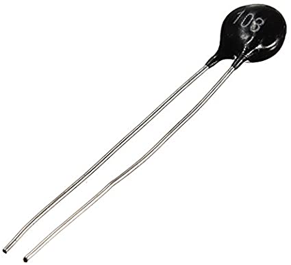 |
10k NTC Thermistor | |
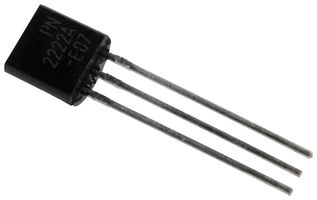 |
General Purpose NPN Transistor | |
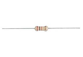 |
1k Resistor | |
 |
10k Resistor | |
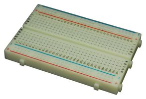 |
Breadboard | |
 |
Jumper wires |
The setup
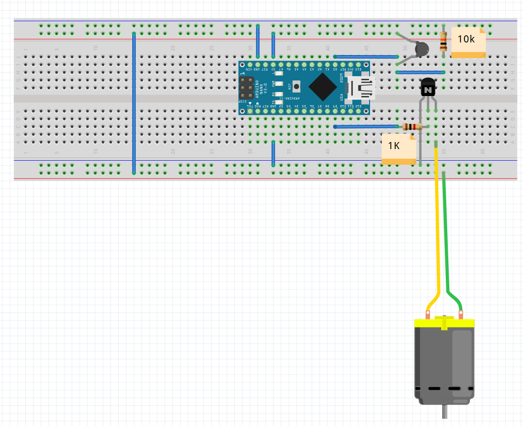
To start, I prototyped the project using a breadboard. A diagram of this is shown below.
The next step was to write some simple software to measure the temperature and set the speed of the fan accordingly. Before I show you the code, it would be best to go over how exactly it all works
How the temperature is measured

Noting that \(V_{out} = V_{k}\), and that the current will be constant throughout the circuit, the proportionality of voltage and resistance stated in Ohms's Law leads to, \[ {V_{out} \over V_{ref}} = {R_k \over R_k + R_T}. \] This can be rearranged into an equation for \(R_T\) as follows, \[ \begin{align} R_k + R_T &= {{R_kV_{ref}} \over {V_{out}}}\\ R_T &= {{R_kV_{ref}} \over {V_{out}}} - R_k \tag{1}\label{eq:resistance_general} \end{align} \]
The voltage meaured by the Arduino is converted into a 10 bit ADC value, with 0 representing 0V and 1023 representing the reference voltage of 5V. This can be described by, \[ ADC = {{V_{out}}\over{V_{ref}}} \times 1023 \tag{2}. \] Plugging this into equation \eqref{eq:resistance_general} yields, \[ R_T = \left({1023 \over ADC} - 1\right)\cdot R_k \tag{3}\label{eq:resistance}. \]
Now that we have an equation for the resistance of the thermistor, we can attempt to convert this into a temperature. In an ideal world this would be done by taking measurements at known temperatures, attempting to fit the results to the Steinhart–Hart equation, \[ {1 \over T} = A + B \ln{R} + C\left(\ln{R}\right)^3, \] where \(T\) is the temperature in kelvin, R is the resistance in ohms and \(A,B\) and \(C\) are model parameters.
As I don't have the equipment to accurately set or measure temperature, I opted to use a simplified equation with only one parameter. The equation in question is derived from the Steinhart-Hart equation by setting \(A = \frac{1}{T_0}-\frac{1}{\beta}\ln{R_0}, B=\frac{1}{\beta}\) and \(C=0\). This leads to, \[ \frac{1}{T}=\frac{1}{T_0}+\frac{1}{\beta}\ln{\frac{R}{R_0}} \tag{4}\label{eq:temp}, \] where \(T_0\) is a reference temperature, usually 25°C (298.15 kelvin), \(R_0\) is the resistance of the thermistor at the reference temperature and \(\beta\) is the sole model parameter.
Equation \eqref{eq:temp} can be used for NTC thermistors, like the one used in this project. Most NTC thermistors will quote values for \(\beta, T_0\) and \(R_0\) in their accompanying datasheets.
We can rearrange equation \eqref{eq:temp} into an equation for \(T\) as follows, \[ \begin{align} \frac{1}{T} &=\ln{\left(\exp{\frac{1}{T_0}}\right)} + \frac{1}{\beta}\ln{\frac{R}{R_0}}\\ &=\frac{1}{\beta}\ln{\left(\exp{\frac{\beta}{T_0}}\right)} + \frac{1}{\beta}\ln{\frac{R}{R_0}}\\ &=\frac{1}{\beta}\ln{\left(\frac{R}{R_0\exp{(\frac{-\beta}{T_0})}}\right)}\\ T &= \frac{\beta}{\ln{\left(\frac{R}{R_\infty}\right)}} \tag{5}\label{eq:temp_resistance}, \end{align} \] where we define \(R_\infty=R_0\exp{(\frac{-\beta}{T_0})}\).